Deposition of complex bandpass filters on aspherical lenses

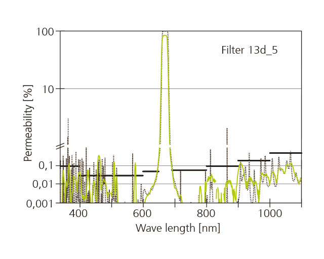
A large proportion of optical components are lenses or aspheres with more or less curved surfaces. Generally, broadband anti-reflective coatings are applied. However, through the deposition of complex filters on lenses, it becomes possible to develop novel, very compact optical systems. Due to the resulting weight advantage, that is particularly interesting for so-called LIDAR scanners (Light Detection and Ranging), which can be installed e. g. on flying objects. At the Fraunhofer IST a coating process has been developed that enables lenses to be equipped with a narrow bandpass filter at a wavelength of 670 nm, which exhibits a very wide blocking range of 300 to 1100 nm. The central wavelength is thereby independent of the position on the lens. This was achieved through a special and well-defined layer gradient on the lens.


Complex coatings on 3D surfaces
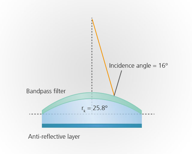
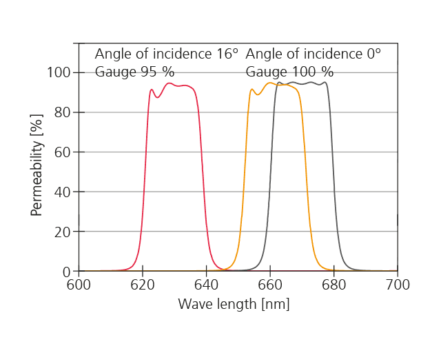
When coating curved optical components, such as a lens, through physical processes, such as vapor deposition or sputtering, a layer thickness gradient is created. The greatest layer thickness is thereby found at the point where the lens is closest to the substrate and the angle to the source is perpendicular. With interference based filters this leads to a shift of the central wavelength. Furthermore, the curvature of the lens causes a shift in the spectrum as the angle of incidence increases. It is disadvantageous that both effects – the decreasing layer thickness towards the edge of the lens and the increasing angle of incidence – go in the same direction, i.e. are cumulatively negative (see adjacent Figure above). In order to achieve homogenization of the coating and therefore exclude at least one of the two effects, ALD processes (atomic layer deposition) are under development today. For ideal compensation, however, a layer thickness gradient is necessary in which the thickness towards the edge of the lens increases accordingly. Magnetron sputtering with a system such as the EOSS® (Enhanced Optical Sputtering System) developed at the Fraunhofer IST is particularly well suited for this purpose, as it delivers outstanding precision and stability.
Lens with bandpass filter
Within the framework of a study funded by the ESA, a bandpass filter was developed and deposited on a lens with a diameter of 25 mm and a focal length of 50 mm. The central wavelength of the bandpass was 670 nm and should exhibit a very wide blocking range of 300 nm to 1100 nm. For this, 207 layers with a total thickness of 23 µm were ultimately required. The suitable layer thickness gradient on the lens was made possible with the aid of a subrotation and an appropriate mask. The determination of the lens shape was performed with the help of the “Particle-in-Cell Monte Carlo” (PIC-MC) simulation. Following this, the mask could be manufactured without further adjustments.
Outlook
In the future, an increasing demand for complex coatings on curved surfaces can be expected. Therefore, the further development of EOSS® technology is the subject of further work at the Fraunhofer IST.
The project
The project was funded through the ESA (contract ITT AO/1-8541/15/NL/PS).