 Fraunhofer Institute for Surface Engineering and Thin Films IST
Examples of cylindrical SIMS specimens with three DLC films and a CrAlN film (drill bit).
Secondary ion mass spectroscopy (SIMS) is a technique used to determine the chemical composition of thin films as a function of the depth. The surface of the specimen is removed layer by layer using an ion beam. SIMS achieves a depth resolution of just one nanometer and detection limits of less than 1 ppm. However, quantifying the depth profiles of thin films is challenging because of so called matrix effects. This means that with SIMS, the calibration factors for the concentrations change with the chemical composition of the specimen, i.e. the matrix. Furthermore, curved surfaces of technical samples pose a particular challenge since they can falsify the results.

Today the automotive and tool industries coat large numbers of small, cylindrical components such as injection needles, piston pins, pistons, drill bits, milling cutters, etc. with hard material coatings such as DLC (diamond-like carbon), tungsten-DLC, CrN, TiN, CrAlN, or TiAlN (see figure above). For the quality assurance of these products it is crucial to measure the hydrogen content (H) of the DLC and W-DLC films or to determine the exact ratio of metal to nitrogen not only at the surface but also in buried layers, multilayers, or gradient layers. By means of quantitative SIMS depth profile analysis this is possible if the Cs-cluster method is used to reduce the matrix effects and adapted standards are applied.

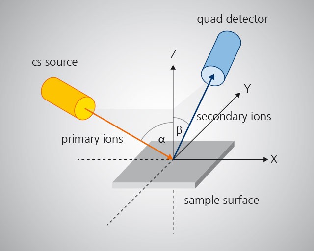
The results of SIMS measurements not only depend on the chemistry of the specimen but also on the impact angle of the ion beam and the take-off angle of the mass spectrometer (see upper adjacent figure). If the ion beam does not hit the highest point of small cylindrical samples with diameters of 2 to 10 mm, the angle of incidence changes (see adjacent figure). For a cylinder with a diameter of 2 mm such as an injection needle, an incidence deviation of just 0.2 mm causes the impact angle or take-off angle to deviate by more than 10°. Since the specimens are optically adjusted and the DLC films are also entirely black, such or even larger adjustment errors can easily occur. This problem plays a special role with curved surfaces.
In a representative study on the aforementioned hard material films, the quantification error as a function of the impact angle α and the take-off angle β was determined in a range of approximately 20° - 60°, where 45° is the standard angle for flat specimens.
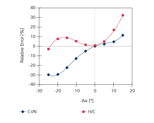
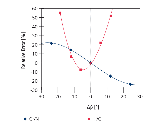
It was found that the raw counting rates for Cr, Ti, Al, W, and N vary by a factor of 5-30 with the angle, the count rates of H, C on the other hand considerably less. The dependence on the take-off angle β is similar in size. For quantification using so called relative sensitivity factors (RSF), the ratio of the counting rates for the elements to the matrix element carbon (C) or nitrogen (N) respectively is determined. This value is proportional to the chemical composition. Thus its variation with the angle α and β indicates the possible quantification error. The graphic below shows exemplarily the error for the H/C ratio of a DLC film and the Cr/N ratio of a CrN film. Especially with H, an angle error of 10° can lead to quantification errors of up to 20 percent which means e.g. that 25at% H instead of 20at% H is detected. The relative error is usually lower for nitride film systems (10%).
The studies show that extremely careful adjustment of the measuring position is of special importance with curved samples. With cylindrical specimens, the ion beam has to be adjusted precisely to the cylinder’s highest horizontal point. Based on the results, for known, well-defined tilt angles, for example a blade cutting edge, the angle dependence can be corrected using the known angle dependence.
This article is part of the annual report 2018.