Fraunhofer Institute for Surface Engineering and Thin Films IST
Scratch track in hard material layer (left), Rockwell spalling in DLC layer (right).
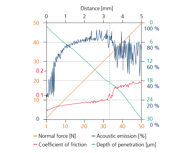
In the scratch test, a diamond stylus is drawn across the surface with an increasing load. During this process, mechanical stresses are generated between the layer and the substrate which lead to layer spalling when a critical limit is exceeded. This critical load serves as a measure of adhesion and is determined by inspection under a microscope. In addition to load and penetration depth, the coefficient of friction and the acoustic emission generated during the scratch test are also detected. This can aid in the evaluation. The device can also be used to test the scratch resistance of surfaces.
In the Rockwell test, a conical diamond indenter is pressed into the surface of the coating with a defined force. Here, too, spalling occurs around the impression, which can be evaluated in accordance with various standards and guidelines. Like the scratch test, the rockwell test is quick and easy to use, but is only suitable for hard and brittle coatings. For soft metals or paints, the recommended procedures are the cross-cut test or the face pull-off test which are also available.
The cross-cut test is a simple method for determining the adhesion strength of coatings. Using a multiple blade, a grid pattern is incised into the coating which is to be tested. After successful cross-cut testing, the surface is cleansed and, subsequently, an adhesive tape (defined in the standard) is adhered to the incised pattern and then removed. The test is evaluated visually (DIN EN ISO 2409) according to the number of flaked/damaged squares and the appearance. Depending on the condition of the damage pattern, cross-cut characteristic values are distinguished from 0 (very good adhesion) to 5 (very poor adhesion).
The pull-off test enables a quantitative characterization of the coating adhesion. Metal stamps (Ø20 mm) are bonded to the coating by means of a 2-component adhesive. Following curing, the force required to tear off the stamp is measured. The torn-off area is measured and its value is subsequently used to calculate the adhesion strength (N/mm2) of the coating. The prerequisite for this test method is a stable bond between the stamp and the coating surface.
An adhesive tape with a defined adhesive strength is firmly adhered to a coated surface and then pulled off abruptly. In the case of good adhesion to the substrate, there is hardly any residue of the coating material on the adhesive tape, whereas in the case of poor adhesion, the coating material remains adhered to the adhesive tape. If the coating material is visible on both the surface of the substrate and on the adhesive tape, it can be assumed that this results from a lack of cohesion within the layer. The tape test serves the purpose of qualitative orientation.