 Fraunhofer Institute for Surface Engineering and Thin Films IST
How is vacuum actually generated? – Part 2

“Wind is air which is in a hurry.” In the Earth's atmosphere, airstreams flow from high-pressure areas to low-pressure areas. We experience them as winds, storms or hurricanes. The Coriolis force forms them into vortices.
Let us look at two containers which, as shown in the adjacent Figure below, are connected to each other via a pipe element and in which differing pressures prevail. If the pressure difference is maintained by the appropriate infeeding of gas to vessel 1, a constant gas stream (pV flow rate) qpV flows through the pipe element.
qpV ~ p1 – p2 = Δp (1)
or
qpV = L · Δp (2)
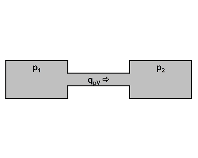
L is the conductance of the connecting element. Its unit is l/s. Equation (2) represents “Ohm’s Law of vacuum technology”, which applies in analogy to Ohm’s Law of electrical engineering if the gas stream qpV is replaced by the electric current I, the pressure difference Δp by the electric voltage U, and the flow conductance L by the electric conductance G (G = 1/R = I/U).
In the case of parallel connection of pipes, the individual conductance values are added to the total conductance value (3), whilst in the case of series connection, the reciprocal values of the individual conductance values are added to the reciprocal value of the total conductance value (4).
LGes = L1 + L2 + L3 + … + Ln (3)
1/LGes = 1/L1 + 1/L2 + 1/L3 + … + 1/Ln (4)
Vacuum pumps reduce the gas density and therefore the gas pressure in a given volume. Two strategies exist for this:
- Transport to atmospheric air
- Binding to a wall which forms part of the boundary of the volume to be pumped out
For the first variant, compression pumps are used; for the second, condensation pumps and getter pumps.
The different pressure ranges from rough vacuum (103 - 100 mbar) to ultra-high vacuum (< 10-7 mbar) are covered by a diversity of pump types; an overview is provided by, for example, DIN 28400.
In addition to the pumping speed (see Newsletter 2/2018), the compression ratio of a vacuum pump, i.e. its ability to compress gases to be pumped, is an important parameter. In the rough and fine-vacuum range up to around 10-2 mbar, rotary vane pumps are primarily used. Gas penetrating from the high-vacuum side is compressed in a periodically increasing and decreasing pump chamber and transported to the atmosphere via an exhaust valve. The compression ratio of a rotary vane pump is around 105, which results in the achievable final pressure. Typical values for the pumping capacity lie at around 50 m3/h.
Roots pumps are dry-running positive displacement pumps which are often used in conjunction with rotary vane pumps. In this combination, final pressures of up to approx. 10-3 mbar can be achieved. In the pump casing, two identical symmetrical rotors, designed in the form of an “8”, “roll” against each other, thereby pushing a specific volume of gas from the low-pressure to the high-pressure side. As a result of design-related gaps between the rotors, the compression ratio is limited to around 102.
Propellant pumps smooth the way from fine to high vacuum. Their functional principle is based on a pulse transfer to the gas molecules. A gaseous or liquid propellant thereby enters the gas chamber at high speed through a nozzle.
Some of our readers may have perhaps already been able to observe the operating principle of a propellant pump in everyday life, namely when showering in a unit fitted with a shower curtain. If the shower head is located in the upper area and the water flows out under high pressure, a slight negative pressure is created in the volume demarcated by the curtain, and the curtain is pulled inwards. The water jet pump and the oil diffusion pump work in accordance with the same principle; the latter will be addressed in the next issue.
Finally, a few words about the water jet pump. Many readers will probably know them from school lessons or studies. For the generation of vacuums in large industrial plants, however, this pump is less suitable. The laws of physics limit the final pressure which can be achieved with a water jet pump. As you may have learned in school, the boiling point of water is dependent on the air pressure (water boils at lower temperatures on the Zugspitze than on the North Sea). The vapor pressure curve of the water shows, for example, that at a pressure of 12 mbar, 10°C “cold” water is already boiling (15°C at 17 mbar). The final pressure achievable with water jet pumps is therefore within this order of magnitude. The pumping capacity of 0.1 - 1 m3/h is also rather modest compared to the compression pumps described above.
In the next article, we will discuss which pump types we use in order to generate high and ultra-high vacuum.
Last modified: