How do you actually make glass “invisible”?
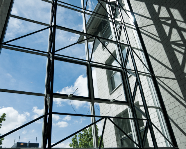
Glass as a material is fascinating due to a number of outstanding properties. The most important of these is its high transparency across the entire visible spectrum, which enables a color-neutral view of the outside world. But let us also take a look at the less pleasant properties of glass. A pane of glass reflects around 8.3 % of the incident light and therefore works like a weak mirror (especially against a dark background). In everyday life, these reflections may not be particularly disturbing, but with high-quality optical components they are not tolerable.
This can be demonstrated using the example of a zoom lens (focal length range 55 mm - 300 mm) from a renowned camera manufacturer. The lens consists of 17 individual lenses, i.e. 34 glass surfaces.
As shown in the adjacent equation (1), the residual light that falls on the image sensor (in the past: film) after passing through the lens is calculated as follows: I/I0 = (0,957)34 = 0,224 whereby I0 is the light intensity prior to entry and I the remaining intensity following exit. For the reflectance of a single glass surface, the value 0.043 [see equation (4)] was used. As can be seen from the result, the light loss lies at around 77 %! Light components, which are created as a result of multiple reflections, “vagabond” through the lens, thereby also causing a reduction in the image contrast.
Lenses with a high-quality anti-reflection coating reduce the residual reflectance to values of around 0.005 (averaged over the visible spectrum between 400 nm and 750 nm) per glass surface. According to equotation (2) I/I0 = (0,995)34 = 0,843 the light losses then lie at around only 16 %.
The operating principle of an anti-reflection coating or coating of optical surfaces can be explained via the phenomenon of interference. A prerequisite for this is the description of the light through an electromagnetic wave.
If such a light wave from a transparent medium with the refractive index n0 (generally this is air with n0 = 1) hits the interface of an equally transparent medium with the refractive index nM, the relationships between transmission, reflection, refractive indices and angle of incidence are described by the Fresnel equations, the detailed discussion of which will be omitted here.
For the sake of simplicity, all observations in this article refer to vertical light incidence. The fact that interference effects are strongly angle-dependent can be observed constantly in everyday life. Take a look at your anti-reflective spectacle lenses or the lenses of binoculars from different angles.
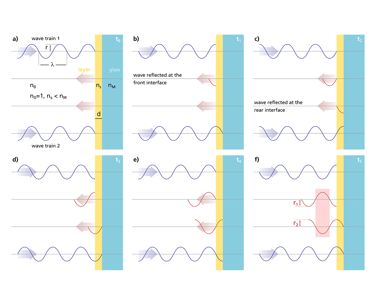
Thin transparent layers on glass can, at suitable refractive indices nS, eradicate (constructive interference) or amplify (destructive interference) the resulting reflected wave. Interference phenomena can then only be observed if the layer thickness lies within the range of the light wavelengths. A graphic representation of the temporal and spatial development of interference at interfaces is best achieved through animations, which are replaced by a number of “snapshots” in this article.

In the adjacent Figure, two wave trains with the same amplitude r and wavelength λ fall in phase on the interface between air and layer at time t0. The following figures 1(b) - 1(f) show the development in time intervals Δt = λ/4c0 with the vacuum light velocity c0 = 3 . 108 m/s.
The wave train reflected at the front air/layer interface precedes the wave train reflected at the rear layer/glass interface by twice the geometrical layer thickness. At a path difference of λ/2, the two reflected partial waves oscillate in inverse phase, thereby canceling each other out [see time t5 in 1(f)]. In principle, the layer can therefore make the glass (or at least its front surface) “invisible”.
In order for a perfect anti-reflection effect to succeed, boundary conditions must be fulfilled. Examination of the illustration immediately reveals that for the layer with a thickness d, precisely “a quarter wavelength must fit in”, otherwise a phase shift of λ/2 is not possible. Furthermore, it should be noted that the light in a medium with a refractive index nS is “slowed down” to the speed c = c0/nS.
The optical layer thickness relevant for the propagation of the wave is therefore nS . d. This results in the phase condition for an eradication of the reflected light: nS . d = λ/4.
The phase condition determines the layer thickness d and can, of course, only be fulfilled for a single wavelength from the visible spectrum (“design wavelength”, in optician-speak). The design wavelength is usually placed in the middle of the visible spectrum (color “green” at 550 nm). In addition to the phase condition, it must also be taken into account that complete eradication can only be achieved if the amplitudes r1 and r2 of the two reflected wave trains are also equal.
As shown in the adjacent formula (6), this results by using the Fresnel equation (3), which is now applied to both interfaces, the amplitude condition for the refractive index nS of the layer is obtained after appropriate conversion.
For the complete anti-reflection coating of glass, a coating material with nS = 1.23 would therefore have to be found, which nature unfortunately does not have in stock for us. With every available material, only a partial eradication is possible. It should be additionally noted that an anti-reflection effect on glass substrates can only be achieved by layers with nS < 1.52; layers with nS > 1.52 lead to increased reflection. The phenomenon can incidentally be observed in everyday life on the “substrate” water (nM = 1.33). Thin petrol or oil residues (e.g. nS = 1.50 for benzene) on puddles create iridescent interference colors.
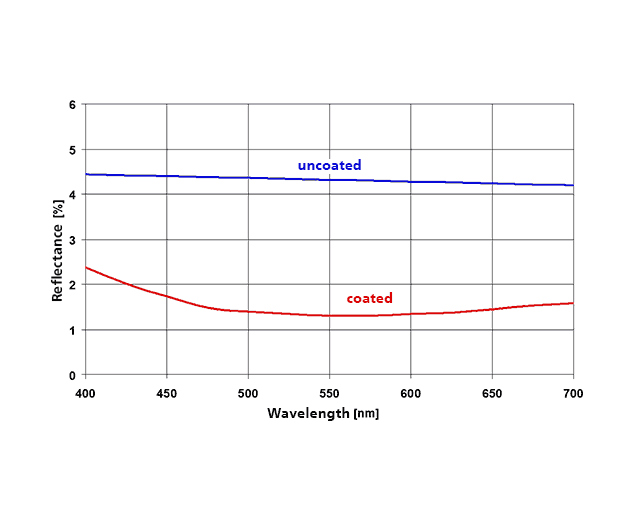
When searching for suitable coating materials with nS < 1.52, MgF2 (nS = 1.38) and SiO2 (nS = 1.46) are encountered. Applying the Fresnel equation to MgF2 yields R = 0.0125 for a glass surface, meaning that the total reflectance of the pane is reduced from 8.3% to 2.5%. This is already a partial success, but potential for improvement still remains. The adjacent Figure shows the reflectance curve of an MgF2 layer with a thickness of λ/4 at a design wavelength of 550 nm. The corresponding layer thickness according to (5) is 99.6 nm.
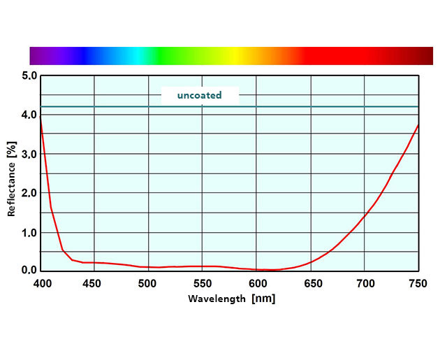
If better antireflection coatings are desired, it is necessary to add “layer by layer”, to apply the Fresnel equations accordingly for several interfaces, and to have suitable designs calculated by the computer. We would like to spare you the description of the progression from the simple λ/4 MgF2 layer through to the super-broadband anti-reflection coating with 6 or more layers. The adjacent Figure shows the spectral reflectance for a broadband anti-reflection coating with four layers comprised of Si02 (nS = 1.46) and TiO2 (nS = 2.35) as the coating material.
An example for the layer structure of such a system is shown in the adjactne Figure. As the reflection from the rear glass surface must also be suppressed, the identical layer package must be applied to both surfaces of the glass.
The adjacent Figure shows an object behind a split pane, where the left half is coated with a broadband anti-reflection coating, thereby becoming practically “invisible”.
The reduction or eradication of reflections for the visible part of the solar spectrum is only one of the challenges which glass presents for us in its function as an optical material or construction element. In addition to light, the sun also provides heat in the so-called near-infrared range (NIR) between around 800 and 3000 nm. Furthermore, during the cold months of the year, rooms need to be heated. The corresponding temperature radiation lies in the far-infrared range (FIR) with wavelengths of around 10 µm.
“Can glass reflect heat?” is a question to which we will provide answers in the forthcoming articles.
Last modified:


